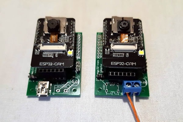
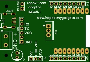
I started playing around with the ESP32-CAM PCB recently and soon discovered what a pain it is to program seeing that it has no onboard USB. To remedy the situation I decided to create my own custom PCB that will allow for easier programming and powering.
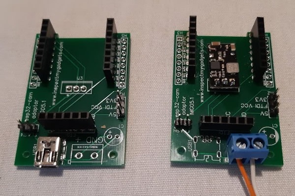
I have tried to keep this adaptor as bare bones as possible while also making it easy for anyone to assemble. As such, the USB socket chosen is a Mini USB type which is a through hole variety and therefore easier to solder. Two Standard 2.54 headers female need to be soldered to the PCB as well to mount the ESP32-CAM to the adaptor, while another one is used for the FTDI connector. This needs to be bent slightly back towards the power sockets to clear the ESP32-CAM or if you use the header with longer leads you could mount this slightly higher so it is flush with the ESP32-CAM PCB. Two other male headers are used to put the device into flash mode and to select the programming voltage from the FTDI adaptor (it is important to set the voltage the same on the FTDI adaptor first as the PCB and also unplug power to the PCB). I generally flash these at 5 volts without any issues but I have seen people swear by flashing at 3.3v, so I have included the voltage select jumper so you make your own choice.
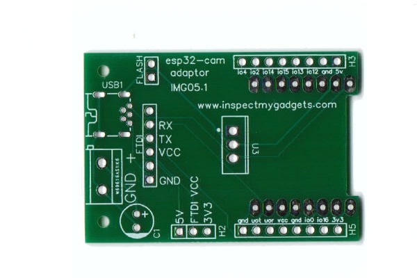
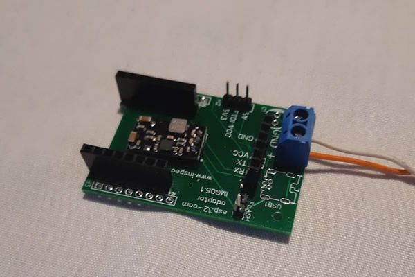
In most cases many would choose to power this PCB by the onboard Mini USB. But I have also included an option to power the device via a DC screw terminal and 5v step down buck converter. This will allow powering the device at higher voltage levels, there is even space for an optional electrolytic capacitor for power filtering. While the pin layout for the buck converter is the same as the standard 7805 voltage regulator, I would advise against using a 7805 due to the heat these create. If you did go one of these I would mount it on the back side of the PCB with a heat sink.
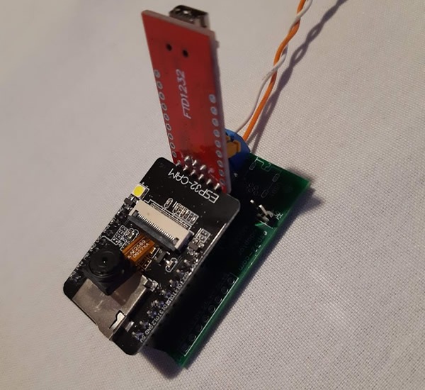
Basic Parts Required
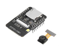
1 x ESP32-CAM
1 x FT232RL FTDI Adaptor (for programming ESP32-CAM)
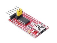
optional FTDI adaptor and ESP32-cam bundled product link
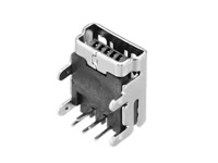
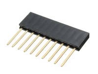
3x female headers (If you have played with ESP32 or ESP8266 boards before you may have plenty of these lying around)
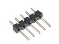
2 x male header
Optional Parts (for DC terminal version)
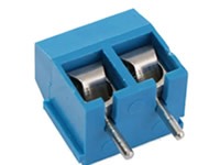
1 x 2 pin screw terminal (replaces the mini USB socket)
1 x 5 volt buck converter (be sure to choose the 5v version)
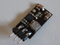
Looking at the component side of the above board the pin layout left to right is, IN, GND, OUT. On the adaptor PCB “IN” is marked with a dot and the board is mounted like below. If you are using the USB powered setup of the board then this component is not needed.
IMPORTANT NOTES
Never connect both the FTDI adaptor to the board while the board is powered. This will most likely blow something up.
Double and triple check the power jumper before attaching the FTDI adaptor. It MUST match what the FTDI adaptor is set to. Getting it wrong will most likely blow something up.
Don’t forget to disconnect both the flash jumper and FTDI connector once you have finished programming the device.
If using the PCB in DC Terminal mode ensure the input voltage does not exceed the input range of the buck converter. The one I linked above has an input rated to 36v, other varieties of buck converter may vary.
If using the PCB in DC Terminal mode chose a stable well regulated power supply, I have found that modern switch mode supplies sometimes give a much cleaner output than some old transformer type supplies. Your results may vary, I have left room on the PCB for an optional filtering capacitor. A 100uf electrolytic capacitor would be my first choice.
If you want your own ESP32-CAM Adaptor you can order it direct from PCBWay Below.
